
Concept
The three-glider system, with identical masses $m$ and spring constants $k$, will have three normal modes characterized by the angular frequencies:
$$\{ \omega_1 ^2, \omega_2 ^2, \omega_3 ^2\} = \left\{ (2-\sqrt{2})\frac{k}{m}, 2\frac{k}{m}, (2+\sqrt{2})\frac{k}{m}, \right\} $$
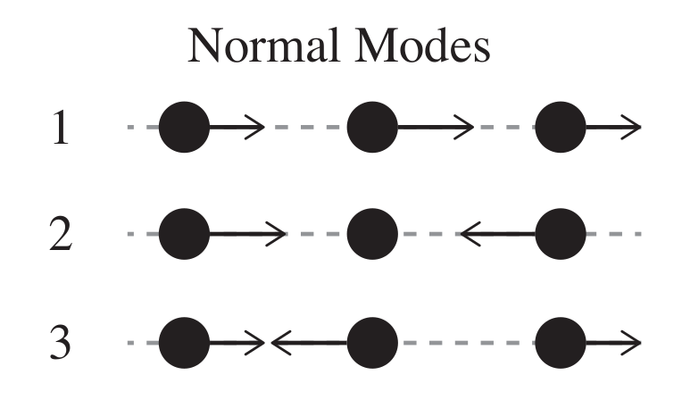
Mode 2 is the easiest to understand, since the middle glider remains stationary as the outer gliders oscillate about it, out of phase, at frequency $\omega_2$. This is conceptually obvious since each outer mass behaves as an independent oscillator attached to two springs with effective spring constant $2k$.
In Mode 1, all three gliders move in phase, at $\omega_1$, but the middle glider has a displacement amplitude $\sqrt{2}$ greater than both of the outer gliders.
Mode 3 has the outer gliders moving out of phase with the middle glider. All three gliders oscillate in simple harmonic motion at $\omega_3$, and again the middle glider has displacement amplitude $\sqrt{2}$ greater than both of the outer gliders.
Procedure
- Turn on the air supply to the air track and the drive switch on the front of the motor.
- Set the driver frequency to 1.0 Hz to tune in Mode 2 (note that this is a linear frequency, $f = 2 \pi \omega$ ). Notice that the glider system enters the second normal mode.
- Adjust the driver frequency to explore the two other normal modes for the system ( $f_1 =$ 0.5 Hz, $f_3 =$ 1.3 Hz).
- Adjust the driver frequency to explore non-normal modes. Notice that the resulting motion is a superposition of the normal modes and beats should occur.
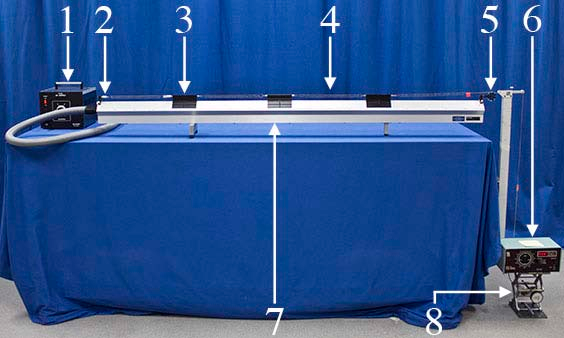
Equipment
- Air Supply and Hose
- (7) Glider-Spring Connectors
- (3) Gliders ($m=$ 225g)
- (4) Springs ($k= 4 \times 10^3 \text{g}/\text{s}^2$)
- Bumper Pulley
- Harmonic Motion Driver
- Air Track
- Lab Jack