
Concept
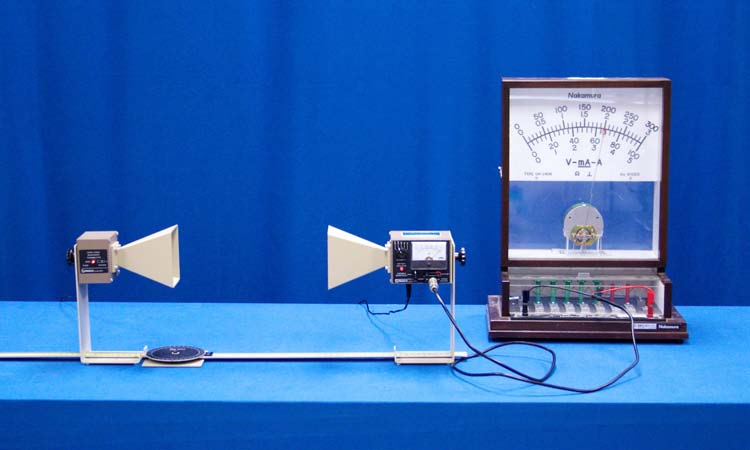
Here’s a vivid demonstration of the existence of electromagnetic waves, in this case those of wavelength on order of centimeters (microwaves). Inside the transmitter horn is a diode oriented vertically that allows for the acceleration of charge within its narrow antenna. The charges oscillate at approximately ten gigahertz within the diode. The constraint that they be accelerated within the boundaries of the diode results in the polarization of the electric field and its associated electromagnetic waves.As the orientation of the receiving horn is rotated, the intensity of the signal correspondingly changes.Two ubiquitous examples of microwave apparatus are ovens and communications towers used to relay cell phone signals.
Procedure
- Verify that the multimeter is set to its 3V setting.
- Verify that the transmitter and receiver are 50 cm apart, plugged in, and oriented in the same plane.
- Turn the receiver knob to the 30x scale and adjust the variable sensitivity until the needle on the receiver reads full scale (1). The multimeter should read about 200.
- Adjust the transmitter’s angle, distance, or polarity as desired and notice how the signal changes on the multimeter.
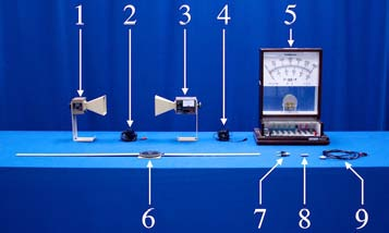
Equipment
- Microwave Transmitter (10.5GHz)
- Transmitter Power Supply
- Microwave Receiver
- Receiver Power Supply
- Nakamura Analog Multimeter
- Goniometer
- BNC-Banana Adapter
- BNC-BNC Adapter
- 3ft BNC-Banana Cable